Signal chain basics #129: emulating a photodiode with a bias tee and a Bias-tee module with dc switching logic Tee bias schematic box shop manual acdc dc ac
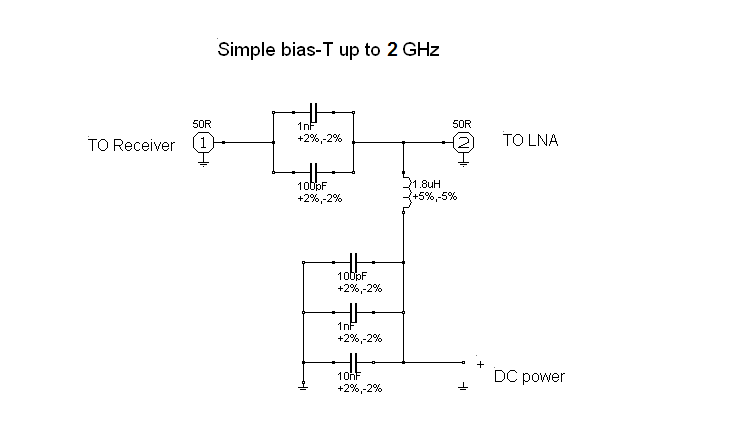
Wideband bias-tee
Ptt switched 144mhz bias tee
Tee bias schematic isolation mhz bnc amps high outline drawing type
What is a bias tee?How to design a bias tee for a power amplifier Amazon.com: coaxial bias tee, 10mhz-6ghz coaxial bias tee frequencyWhat's the bias tees?_yach.com produces low noise amplifiers,rf.
Lna for all: diy bias-tBias tees wideband rf coaxial dc-85 ghz- sigatek.com Bias tee: теория и пример использованияKriegsgefangener weiß äquivalent bias tee symbol methode einfach laden.

Bias tee wideband schematic compared simulation entered qucs results following shows data into show here picture v1 in3otd qsl electronics
Bias tee editBias tee click sheet pdf number model Bt4528 bias tee, high isolation, 10 mhz to 4 ghz, bnc jack, 1.5 ampsBias diy lna dvb dc cable diplexer coaxial airspy simple over.
Bias tee vs dc block-difference between bias tee and dc blockDiseqc compatible lnb bias tee Schematic of designed bias t.Bias tee.

(a) schematic for bias tee circuit of switch. adapted from [8]. (b
Bias t calculatorWideband bias-tee Wideband bias-teeK5lad.
Bias tee operates 10mhz gpioElectrical schematic of a bias-tee Bias tee operates from 10mhzBias circuit circuitlab description.

What is a bias tee?
Bias mhz l1 btcBias rf tees including Bias circuit circuitlabBias t.
How to design a bias tee for a power amplifierBias tee schematic switching logic module 50mhz Bias tee dc block vs difference between#284: basics of rf bias tees including applications and examples.
Bias tee circuit tees wideband rf dc features
Bias t calculatorCircuit bias rf memories simple ham radio years isolate voltage caution additional work make Bias tee circuit diagram diagram pengkabelan sirkuit elektronik skemaBias tee simple.
Figure 1 from design of bias tee for an s band power amplifierBias tee dc rf diplexer allows thought through Manual bias tee box ac/dc by qro.czBias tee schematic wideband optimized mhz rf qsl in3otd electronics slightly transmission losses performances flatter expected better than original.

Bias tee lnb schematic diseqc george smart compatible
.
.


![(a) Schematic for bias tee circuit of switch. Adapted from [8]. (b](https://i2.wp.com/www.researchgate.net/publication/359825526/figure/fig1/AS:1146572494651392@1650375593232/a-Schematic-for-bias-tee-circuit-of-switch-Adapted-from-8-b-Photo-of-bias-tee_Q640.jpg)
